Full Text
Introduction
This HubLE Method is about all the morphometric parameters that microCT can measure in bone. What do they mean? Which ones are important for my genetic / disease model?
Materials
- uCT scanner, with powerful PC: min 32Gb RAM, preferably Nvidia GPU.
- Reconstructed uCT bone datasets
- Software for 3D morphometric analysis of bone including flexible VOI selection and thresholding / segmentation (making black and white images) and 3D analysis equipment
Methods [Update]
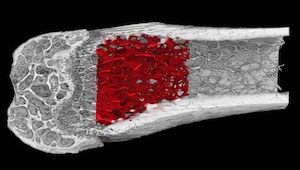
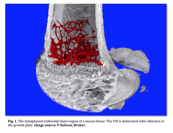
- For characterisation of trabecular and cortical bone, in osteopenia studies or general bone phenotype studies, the VOI is standardised relative to the growth plate2.
- For study of subchondral bone at the knee articulation between femur and tibia in arthritis, the appearance of a connecting bridge in cross-section between the two condyles can be used as a reference point.
- For study of bone disruption (osteolysis and pathological formation) by bone tumour metastases or myeloma, a segment of the metaphysis should be selected relative to either the growth plate or the end of the bone (junction of condyles). Note that severe osteolysis can complicate VOI selection since large parts of bone structures can be missing.
- For study of a fracture callus, identify the fracture midline and choose a fixed number of cross-section slices on either side of this point, such as 100-200 slices on both sides.
- For cartilage, for instance if a rodent knee is stained by a contrast agent such as phospho-tungstic acid, regions of the medial condyle articular cartilage can be selected where the condyles are separated, not touching each other, for easier VOI selection.
- Drilled bone cores need only a cylindrical VOI in the middle of the specimen to avoid damaged tissue.
- Use 3D software tools to delineate the VOI, either by manual drawing or automatic delineation, carefully referencing the VOI to anatomical landmarks3
Tips [Update]
Parameter name; ASBMR nomenclature4 symbol; Unit; What it is, how to use it:
Bone volume; BV; mm3; The absolute quantity of bone by volume, within your VOI.
(Remember – a consistent VOI is important!). The 2D equivalent is cross-sectional bone area, BA.- Percent bone volume; BV/TV; %; If your VOI is fully contained within bone, such as a region of medullary marrow space containing trabecular bone, then BV/TV is the key parameter of the spatial density or occupancy of that VOI. Note however that if a VOI extends beyond bone arbitrarily into surrounding space, such as a VOI drawn around the outside of cortical bone or a fracture callus, then BV/TV is not relevant. The 2D equivalent is % bone area to total area, BA/TA.
- Bone surface to volume ratio; BS/BV. mm-1; A useful general indicator of structural complexity and inversely related to bone or trabecular thickness. Can be in 2D (perimeter / area) or 3D (sfc. / vol.).
- Trabecular (Cortical) thickness; Tb.Th (Ct.Th); mm; 3D thickness measured by virtual sphere-fitting.
- Trabecular separation (pore diameter); Tb.Sp (Po.Dm); mm; Diameter of spaces measured as Tb.Th.
- Trabecular number; Tb.N; mm-1; The spatial density of structures within a VOI such as trabeculae. It is computed as the number of times per mm a random line through a VOI crosses a trabecula. Tb.N can be calculated from (BV/TV)/Th but a 3D calculation as 1/(Tb.Th+Tb.Sp) is more accurate.
- Trabecular pattern factor; Tb.Pf; mm-1; Alternatively called surface convexity index (SCv.I). Convex curvature moves the index in a positive direction, while concave curvature makes the index negative (flat is zero). It is an inverse indicator of connectivity since multiply connected structures – such as healthy trabecular bone – have a lot of concave curvature at their nodes and thus low or negative values. Tb.Pf and SMI (next) are measured by the same differential method and are useful measures of “texture” of fracture callus and pathological ectopic bone formed in arthritis and tumour models.
- Structure model index; SMI; None; SMI like Tb.Pf measures surface curvature. In ideal shapes a flat plate, a cylinder and a sphere have SMI of 0, 3 and 4 respectively. SMI has been criticised (5) for expectation of these ideal shape model values ignoring concave curvature of node connections, and for its % volume bias; however it remains a useful parameter of architecture if correctly interpreted.
- Fractal Dimension; FD; None; This parameter looks for repetition of similar structures on different spatial scales – like a fern leaf. A useful general index of complexity in bone disruption models.
- Euler Connectivity (density); Conn (Conn.D.); None (mm-3); Euler topological connectivity counts the number of loops or alternative connections. It can show loss of connections in osteoporotic bone.
- Degree of Anisotropy; DA; None; Are trabecular structures aligned in one direction – e.g. of mechanical loading? Then DA is high. If not, DA is low. DA increases as fracture callus remodels to cortical bone.
- Moment of Inertia parameters; MMI; mm4; MMI parameters are defined around an axis. This can be the X or Y axis of a cross-section plane, or the Z axis. It helps if your software calculates the maximum and minimum axes of inertia (strongest and weakest direction). Things break in their weakest axis. There are many MMI indices such as x, y, polar, principal min and max.
References [Update]
Salmon PL (2020) Micro-computed Tomography (micro-CT) in Medicine and Engineering; Orhan K ed, Springer Nature Switzerland, pp. 49-75.
van ‘t Hof RJ, Dall’Ara E. Analysis of Bone Architecture in Rodents Using Micro-Computed Tomography. Methods Mol Biol. 2019;1914:507-531.
Bouxsein ML, Boyd SK, Christiansen BA, Guldberg RE, Jepsen KJ, & Muller R. Guidelines for assessment of bone microstructure in rodents using micro-computed tomography. J Bone and Miner Res, 2010;25:1468–1486.
Dempster DW, Compston JE, Drezner MK, Glorieux FH, Kanis JA, Malluche H, Meunier PJ, Ott SM, Recker RR, Parfitt AM (2013) Standardized nomenclature, symbols, and units for bone histomorphometry: a 2012 update of the report of the ASBMR Histomorphometry Nomenclature Committee. Journal of Bone and Mineral Research 28(1): 2-17.
- Salmon PL, Ohlsson C, Shefelbine SJ, Doube M (2015) Structure Model Index Does Not Measure Rods and Plates in Trabecular Bone. Front Endocrinol (Lausanne). 2015; 6: 162.